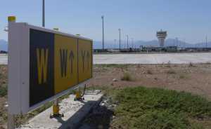
The IR858I taxiway guidance sign is the latest LED model of airfield sign to be manufactured by atg airports. This airfield sign is certified to meet the ICAO requirements for Mandatory and Information requirements. (ICAO Annex 14, MOS, TP312)
Taxiway Guidance Signs IR858i – Installation Guide
Product Overview
Introduction
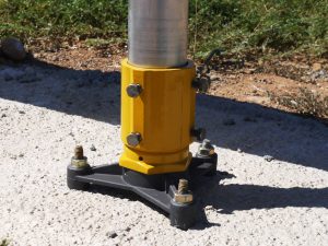
ATG Airports Ltd IR858 signs require installing onto a concrete base, using foot mounts, frangible couplings & 60mm diameter aluminium poles. The sign is secured to the poles using the supplied brackets.
Manual handling
Airfield signs can be up to 3 metres in length may be heavy to manoeuver. Methods of handling must be considered before attempting to install the sign. A full list of sign lengths and weights is available in the user manual

Installing signs using the foot and frangible coupling
A level concrete base should be constructed as appropriate for the size of the sign. The foot can then be secured to the concrete base using the appropriate bolts. The number of poles and the distance between them depends on the length and height of the sign and the mode type (See FAA AC150/5345-44K.) Mode 2 signs are designed to withstand a wind speed of 200mph (322kph). Mode 3 is designed to withstand a wind speed of 300mph (483kph). The number of poles required for each mode type is provided in the user manual.

Installing signs using the foot and frangible coupling
It is absolutely imperative that, when more than two poles are required, all the poles must be mounted exactly in line. If this is not done, fastening the sign to the poles can cause twisting and damage to the sign.
When the foot mounting has been secured to the concrete base, screw the frangible coupling into the foot until hand tight. Using a 70mm spanner or similar tool, apply an additional one quarter turn to fully secure the coupling in place. Insert the poles into the frangible coupling and tighten the four hexagon bolts on the side of the coupling.

Fixing signs to the poles
Great care should be taken when handling long signs to ensure that the sign body does not twist in any way, as this may result in damage to the sign.
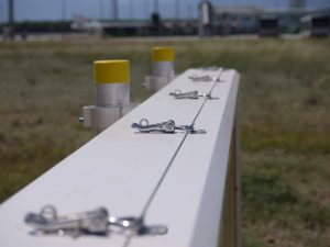
Lift the sign vertically against the poles and support it off the ground on wooden blocks or similar, so that the top of the sign is at its correct height. Position the sign so that the distance from the end of the sign to the pole at both ends is equal. The sign should then be set such that it slopes very slightly to one end. This will ensure that any condensation which may form inside the sign will drain out. (Slope of 1:100). Attach the fixing bracket around the pole and position onto the bottom lower mounting ‘U’ profile on the back of the sign. Fasten lightly until it just grips the sign. Repeat for the bottom bracket on each pole on the sign, then the top bracket for each pole. Check that the sign is in its correct position and adjust if necessary. Tighten all the clamps on the poles and remove any packing from beneath the sign, ensuring that there is no movement on the poles. The poles should not protrude above the sign case and if necessary these should be cut short. Finally fit the plastic cap over the top of each pole.


